
I have read an article on the teardown of a dashboard mileage manipulator dongle on Hackaday. A “CAN bus filter” device was found in a vehicle, connected to the back of its instrument cluster. When it was removed and the original connections were restored, the odometer immediately showed 40 000 kilometers more than before. The author made a quick teardown and analysis on the device but because it was supposed to be locked (according to the article), the firmware was not extracted, leaving the big question unanswered:
What it does and how it does it?
Mileage manipulation is illegal in many countries and one could easily go to jail if kept doing it. Still, this is quite common practice on the used car market and mileage manipulator devices could be easily purchased by anyone. The main purpose of these “greyish” tools is to mislead and to fool the buyers. Considering this, I was happy to extend my “to be hacked” list with them, and I also wanted to see how they work and if there is anything to do against the “attack”. Everything was set for a cool project combining car hacking, hardware hacking and reverse engineering. Due to the nature of the topic, I expect readers with less relevant technical knowledge as well, so I tried to provide a bit more details and explanation, to make sure everyone can follow along.
These boards can be found on eBay for $15-25, e.g. by searching for “18 in 1 Universal CAN Filter“. Several sellers are providing them under different fantasy names and with some variance in their supported vehicle list. I decided to order two type of CAN filters from two different sellers. They had the same functionalities, but their PCB looked a bit different. Both CAN filter devices support a bunch of car models from two major German OEMs (just look for the description in the eBay product pages). After one makes the mileage manipulation, this device will prevent the odometer’s sync and increase, by manipulating the relevant communication. For easier reference, I am calling them as #blue CAN filter and #green CAN filter in the following sections.


The devices are designed to be connected to the CAN bus in a MITM (Man In The Middle) setup, by intercepting the CAN communication between the instrument cluster and the rest of the car. The circuits are quite simple. By identifying the main components and following the PCB traces I reversed the schematics. At the first look there are some trivial differences in the HW design and in the components used, but the main structure is identical. Both boards use the STM32F105 (STM32F105RBT6 to be precise) general purpose microcontroller. Its notable features are: 32 bit ARM Coretex-M3 core, 128k flash, 64k SRAM, Serial Wire Debug (SWD) and JTAG interfaces, 2x CAN interfaces. There are solder jumper pads connected to the MCU’s GPIOs (PC10, PC11, PC12 and PA15) for device configuration, 2 CAN transceivers to drive the physical CAN bus, and 2 LDOs providing regulated 3.3V for the MCU and 5V for the CAN transceivers. Config selector solder jumpers, when shorted, are actually pulling the given GPIOs to ground. As there is no additional resistor connected to these pins, the GPIOs should be configured to input, with internal pull-ups. This means that their default read value is logic high until the solder jumper config does not pull them down to ground. The only meaningful difference between the two boards is that the #green CAN filter device exposes serial programming connections (PA9/USART1_TX, PA10/USART1_RX together with BOOT0 boot mode selector), while the #blue CAN filter board exposes the SWD debug interface (PA13/SWDIO, PA14/SWCLK and BOOT0 pins) on the unpopulated pin headers. Note that the #green CAN filter also exposes the SWD connections, but on small test points only.


Obvious next step is to connect to the debug and programming interfaces to try to download the firmware. Normally, this should not be possible, because with basically zero effort the debug access could be easily disabled, and firmware readout could be also prevented. Important to mention that we are talking about a general purpose microcontroller, which is not supposed to be resilient against advanced HW hacking attacks, that can be used to bypass the applied protections. Nevertheless, using the device provided security features is the bare minimum to raise the bar for the attackers.
With unrestricted access to low level debug interfaces, such as JTAG or SWD, one could take full control over the device, such as stopping and altering the code execution, accessing memory and registers, or even dumping the firmware. There are circumstances, where debug access is possible, but its features and memory access are limited. For example, flash dumping is not possible, so this should be always tested according to the given device’s security features.
For this test, I flashed the Black Magic Probe firmware (JTAG/SWD debugging tool, with built-in GDB server) to my custom HW hacking interface and connected it to the exposed SWD connections (PA13/SWDIO, PA14/SWCLK) on the #blue CAN filter. After powering on the environment just couple of steps were needed:
- With ‘arm-none-eabi-gdb’ (architecture specific GNU debugger) I connected to the Black Magic Probe remote GDB server
- With ‘swdp_scan’ available device was checked on the SWD interface
- After attaching to the identified target device, access to registers and memory were checked
- Then a simple ‘dump memory binary’ command targeting 0x08000000 address (where the flash memory is mapped, see memory mapping from datasheet) was executed
Voila, the firmware was dumped. Surprisingly, the “vendor” did not make any effort to lock down the MCU. Access was not restricted neither to the debug interface nor to the flash memory. I was surprised and to be honest, disappointed a bit.


Knowing the results from the #blue CAN filter investigation, I did not expect anything harder to extract the firmware from the second device. In this case, access to the serial bootloader was the very first test to do. I connected the serial pins (UART RX/TX) of my HW hacking interface to the exposed serial pins (PA9/USART1_TX, PA10/USART1_RX) on the #green CAN filter and wired the device’s BOOT0 pin directly to 3.3V. When the BOOT0 is high on reset, the MCU boots to the “system memory boot mode”, making interfacing with embedded bootloader possible through its USART1 (Universal Synchronous and Asynchronous Receiver-Transmitter) interface. One tool to communicate with the embedded bootloader over serial is stm32flash. Missing protection on the device was also confirmed by using its read flash functionality as well as it made the firmware download simple with one single command.

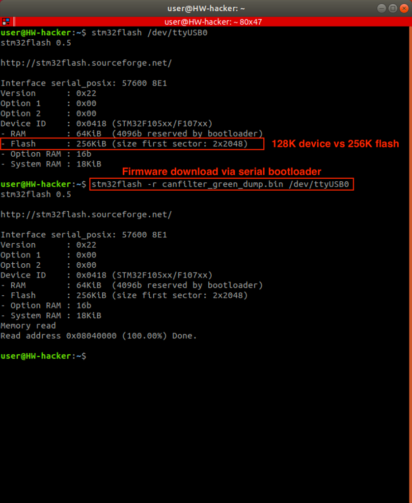
Oh, did you recognize that 256k flash was reported and read by the tool, instead of the expected 128k? We have seen this many time with STM32 MCUs. This is not always the case, but you often receive the bigger flash version when buying the smaller one, meaning the label shows the smaller version, but the HW actually is the larger config.
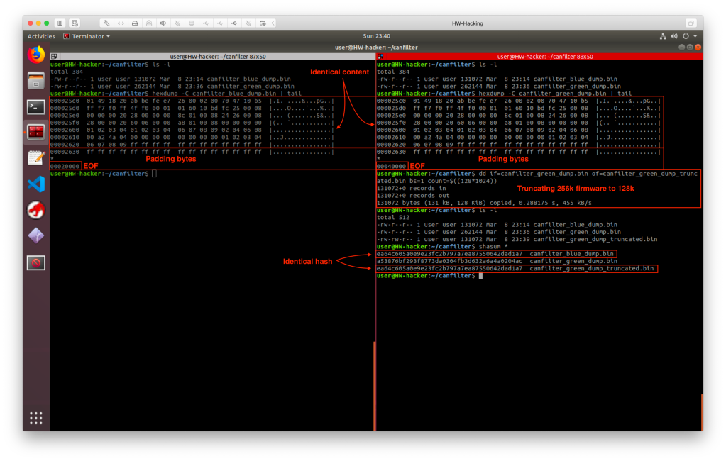
So, I extracted the firmware from both device variants, without any serious hardware hacking. Let’s ignore the shameful circumstances and have fun with the firmware at least. As my CAN filter variants are almost identical and they have the same functionalities, I thought it would be a good idea to take a look into the extracted binary firmwares before starting the reverse engineering. The code should not be too complex, so there must be a bunch of free space at the end of the flash, which is usually filled up with 0xFF. Firmware extracted from the #blue CAN sniffer was 128k and the one from the #green CAN sniffer was 256k. I checked the binary firmware images with ‘hexdump’. The last bytes of the exact code finished at the same address and the bytes were also identical. Just the amount of the 0xFF padding bytes were different, due to the size difference between the two images. Then I truncated the 256k flash image to 128k with ‘dd’ and checked the firmware images’ SHA hashes. They were identical, which means the two devices have exactly the same firmware, and it also means less reverse engineering work for me. 🙂
As the device is manipulating the CAN communication (see CAN bus on Wikipedia), let’s highlight the most relevant details. While speaking about CAN without specifying additional details, such as CAN-FD or CAN2.0B, most of the time we are talking about CAN2.0A, that has a data frame with 11 bits ID (also referred as CAN ID, message ID or frame ID), 4 bits of DLC (Data Length Code, the “payload” length indicator) and maximum 8 bytes of data, the useful payload in the frame. We should focus now only on the ID and Data.

Jumping back to the track, do you remember the big question? What the device does and how it does it? Having this in mind I started the reverse engineering.

The MCU is ARM Cortex-M3 which is widely supported by reverse engineering and disassembler tools. As the target is a bare-metal firmware, as it is running directly on the MCU without any additional OS layer, special attention should be paid to references to memory addresses, because peripherals are mapped to specific memory locations. Interfacing with and controlling the peripherals are possible by reading or writing these addresses.
I used Ghidra for reverse engineering together with the SVD-loader Ghidra script, which helps resolving peripheral related or other function specific memory addresses, based on device specific SVD (System View Description) files. Every information needed to understand the peripherals, interfaces, control registers, their bit mappings etc. are available along with all details in the corresponding STM32F105xx reference manual.
Analysis of these firmware usually starts with the vector table investigation, where pointers for the reset and other interrupt handlers (also called as ISR, Interrupt Service Routine) are. A quick look into the vector table reveals some interesting entries besides the reset handler, such as the CAN message interrupt handlers.


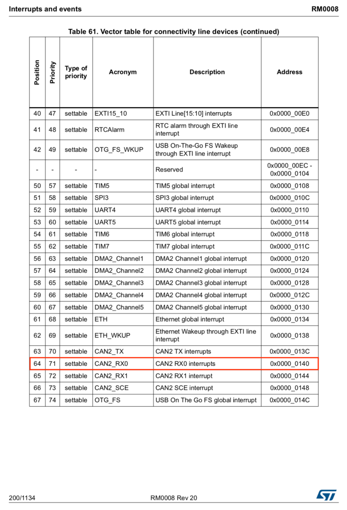


Code in the reset handler and in the identified main function does nothing but some minor suff after the usual clock and peripheral setups. The magic however, can be found in the CAN1_RX0 and CAN2_RX0 interrupt handler routines. These interrupts are triggered when new CAN frames are captured and parsed on the CAN interfaces. The graph views of these routines immediately show patterns for several branches, which is expected due to the car configuration and CAN message dependent manipulation requirements. Remember, the device configuration is controlled by the solder jumpers and consequently by the logic level of their connected GPIOs. When a configuration is selected, its GPIO is tied to ground, logic low, resulting in 0 when its value is read. This can be seen from the code as well, when given GPIO value is tested for zero during the message processing.


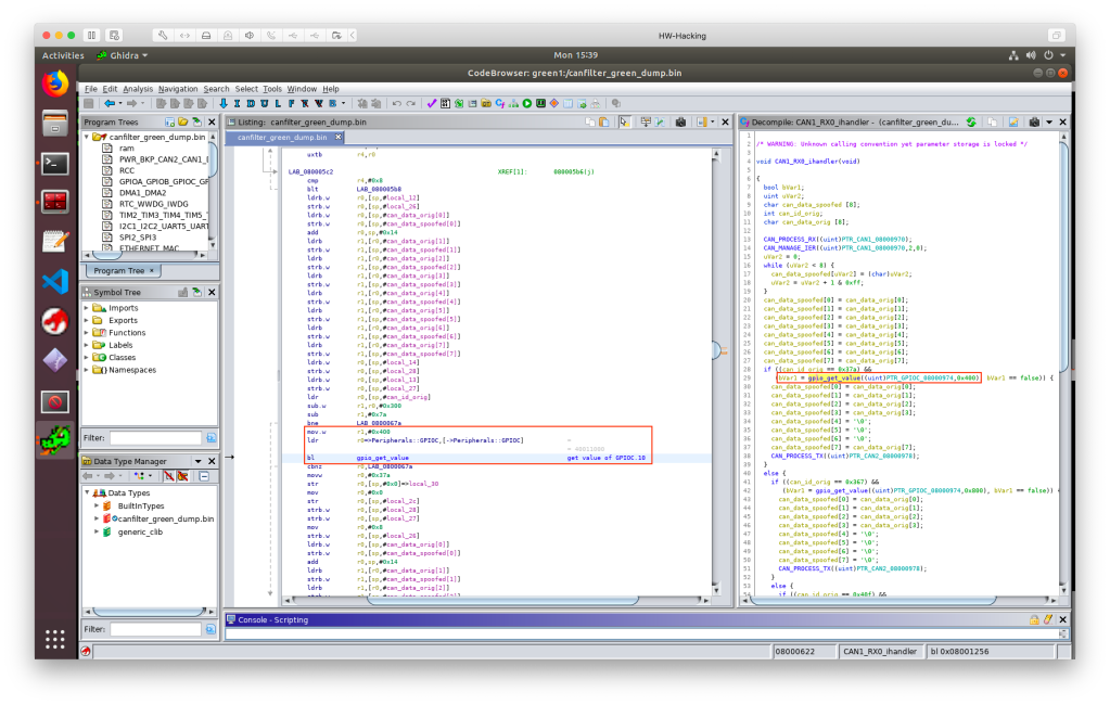
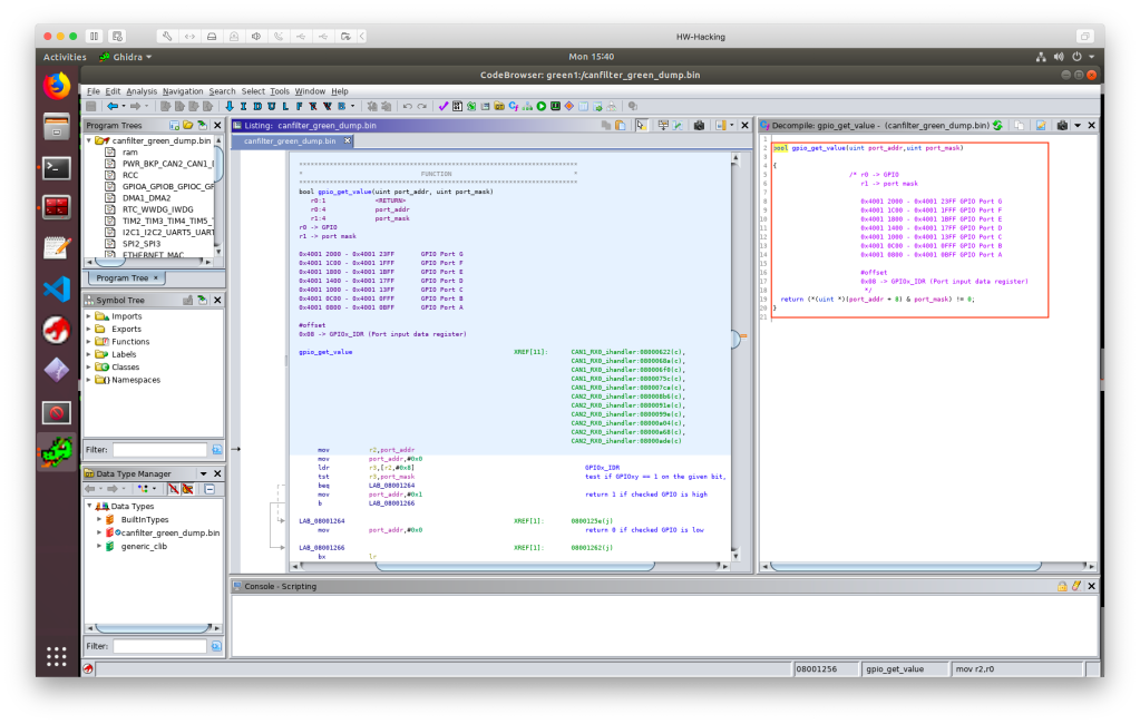


To show an example on memory mapped peripherals, take a look into the ‘gpio_get_value’ routine. It is called by passing two arguments, the given GPIO Port Register’s base address in ‘r0’ register and a “bit mask” in ‘r1’ register. From the base address + 0x08 the “Input Data Register” (IDR) is referenced, where the given GPIO values (0 or 1) are stored. The return value is calculated by bitwise AND between the provided “bit mask” and the IDR’s value. In this example the port register base address is 0x4001 1000, that belongs to PORT C (PC), the “bit mask” is 0x400 (binary 0100 0000 0000, meaning the ‘1’ bit is at the IDR10 location), which means the routine will return with the PC10 GPIO value.
CAN_PROCESS_RX processes the captured data frame and copies the relevant data from the CAN interface registers to a data structure on the stack. This is from where the CAN RX ISRs also accesses the CAN packet’s details. CAN_MANAGE_IER manages the CAN Interrupt Enable register, in this case it disables it for the given CAN interface. CAN_PROCESS_TX sets up every relevant data in CAN mailbox registers to transmit a CAN message. The essence of the whole firmware is located in the CAN RX ISRs, so I just skip the explanation of general or not that interesting routines and code parts.
As it can be easily seen from the decompiled code, CAN RX ISRs work in the following way:
- Process the incoming CAN frame
- Temporarily disable the CAN RX interrupts on the given interface (it is re-enabled in the main routine’s while(1) loop)
- Zero out the spoofed CAN payload buffer
- Fill the spoofed CAN payload buffer with the captured CAN data bytes
- Check for specific CAN ID
- If interesting ID is identified, then check if it is applicable for the current car config, by checking the corresponding config selector GPIO’s value
- If CAN ID and the car config match, apply the message specific payload byte manipulation (e.g. zero out specific bytes in the message) then send out the manipulated message on the opposite CAN interface
- If no match was found with the CAN ID and with the given GPIO config, then jump to the next check and repeat from step #5 until there is more ID to look for
- If no match was found at all, then forward the message to the opposite CAN interface without modification
By the way, did you recognize strange code sections?
- In some cases, interrupts (either all of them or only the one that belongs to the ISR) should be temporarily disabled, to let the handler routine run without any disturbance, e.g. preventing inconsistency while working on variables or input data. The firmware’s author disabled the CAN_RX interrupt only after calling the CAN message processing routine, leaving a possible problem in the firmware that might be triggered under special circumstances. CAN_RX IRQ should be disabled at the very beginning of the ISR. Moreover, the disabled IRQ could be simply re-enabled at the end of the ISR, so I do not see any reason to enable it continuously in the main’s while(1) loop.
- CAN filtering depends on the solder jumpers and their corresponding GPIO status. The code, called from the interrupt handler, reads the GPIO values every single time it processes a CAN message with the monitored IDs. This simply makes no sense, it is useless and “time consuming”, especially in an interrupt handler routine. ISRs should be as fast and as short as possible. Moreover, no one will change the car config (meaning re-soldering the solder jumpers) on the device while it is running. This config should be read once after reset and the config should be kept in a variable.
- There are branches, where CAN_PROCESS_TX routine is called twice in a row for no reason. Maybe just a copy-paste issue.
- You may not see the whole code, but there is no reference to the 4th solder jumper config, that belongs to PC12 GPIO, meaning that the full capabilities of the HW is not utilized at the moment. Additional car configurations and filters could be added just by firmware modifications – no HW upgrade is needed.
The code actually works, but good practices are not always followed and it seems to be a quick and dirty implementation, maybe copy pasted from googled code samples. 🙂
So far so good, I understood the firmware and its CAN packet hot-patching functionality via its MITM (Man In The Middle) approach. I wanted to confirm the theory and see it in practice. Unfortunately I did not have access to a CAN filter compatible car and buying one only for this purpose was over the planned budget 🙂 so I created an artificial test setup.
Two USBtin devices were connected to a linux machine. These are cheap SocketCAN compatible USB to CAN interfaces, which means that can-utils could be used to simply interact with the CAN bus. The CAN interfaces were configured to 500 Kbit/s bus speed, that is also expected by the CAN filter device. USBtin#1 was connected to the #green CAN filter device’s CAN#1 port, while USBtin#2 was connected to the filter device’s CAN#2 port. I started monitoring the CAN interfaces while specific CAN messages, based on the extracted details from the firmware reverse engineering, were sent out through the USB CAN interfaces.
Overview on the test setup:
                    --------
          /---------|  PC  |---------\
          |         --------         |
   slcan0 |                          | slcan1
     ------------              ------------
     | USBtin#1 |              | USBtin#2 |
     ------------              ------------
          |                          |
          |      --------------      |
          \------| CAN filter |------/
            CAN1 -------------- CAN2


As per the used solder jumper configuration (option “W166”, connected to PC10 GPIO), the firmware looks for 0x37A CAN message ID on its CAN#1 interface, while it looks for 0x3D9 and 0x19F message IDs on its CAN#2 interface.
In case #1, when I was sending irrelevant messages through the USB CAN interfaces for both directions, the CAN filter simply forwarded the CAN frames without any modification (note the slight delay from the timestamps, that is needed to forward the message). The same happened in case #2, when a message with monitored ID was sent out, but in the wrong direction. However, in test case #3 when I was sending a CAN message that matched the criteria in the current configuration, the CAN MITM hot-patching started to work and did its job. In this example ’37A#CAFEBABEDEADBEEF’ message was changed to ’37A#CAFEBABE000000EF’ on-the-fly.


Theory confirmed. Although the exact meaning of the payload bytes from the filtered CAN frames is unknown and it is out of scope of the current investigation, it is pretty clear what the device does and how it operates:
- it implements an active MITM (Man In The Middle) attack between the instrument cluster and the rest of the car / gateway module
- based on its configuration (defined by GPIO values controlled by the solder jumper setup) it looks for car specific messages
- not interesting CAN frames are simply forwarded by the device
- interesting car specific CAN frames are captured and hot-patched before forwarding
To be more precise, the table below summarizes what the device does, how it hot-patches CAN messages between the instrument cluster and the car in different configurations.
Legend: "XX" -> not changed, otherwise hot-patched as per the value showed

| CONFIG     | COMM. DIR. | ID  | PAYLOAD CHANGE PATTERN  | CONDITION
---------------------------------------------------------------------
| W166(PC10) | CAN1->CAN2 | 37A | XX XX XX XX 00 00 00 XX |
| W166(PC10) | CAN2->CAN1 | 3D9 | XX XX XX XX 00 00 00 XX |
| W166(PC10) | CAN2->CAN1 | 19F | XX XX XX XX XX 00 00 00 |
| W222(PC11) | CAN1->CAN2 | 367 | XX XX XX XX 00 00 00 00 |
| W222(PC11) | CAN1->CAN2 | 40F | XX XX XX XX 00 00 00 00 |
| W222(PC11) | CAN2->CAN1 | 367 | XX XX XX XX 00 00 00 00 |
| W222(PC11) | CAN2->CAN1 | 40F | XX XX XX XX 00 00 00 00 |
| BMW(PA15)  | CAN1->CAN2 | 5C0 | XX XX 00 00 00 00 00 00 | if CAN.DATA[0] =='H'
| BMW(PA15)  | CAN1->CAN2 | 394 | XX XX 00 00 00 00 00 00 | if CAN.DATA[0]=='H' and CAN.DATA[1]=='\0'
| BMW(PA15)  | CAN2->CAN1 | 330 | 00 00 00 XX XX XX XX XX |
| BMW(PA15)  | CAN2->CAN1 | 5C0 | XX XX 00 00 00 00 00 00 | if CAN.DATA[0]=='H'
One, who is interested in the exact meaning of the bytes and the data representation in the interesting CAN frames, should capture valid messages in a real environment and make some correlation analysis on the captured data and the represented values from the odometer. Most probably, reporting of real odometer values from other ECUs are blocked (that should set up the right value e.g. in a new/replaced instrument clusters) as well as messages which should increment the stored odometer value by sending the distance travelled. This is however out of my interest and I consider the hacking and reverse engineering done at this point.
I was really surprised that no protection was applied at all on the MCUs. My assumption was that device makers, including this greyish area, try to make their competitors life at least a little bit harder to prevent them from reversing and replicating their products.
Unfortunately, detecting and preventing these attacks are not easy on CAN bus. ECUs have no clue whether the received data frames are manipulated or not, as the protocol does not offer any solution to validate the message’s authenticity and integrity (excluding the frame integrity, but that is for different purpose). One way to deal with this problem is to use e.g. MAC (Message Authentication Code) and freshness values, but the standard 8 bytes length CAN data frames do not provide enough room for a proper implementation.
It was not a big deal, right? One, who knows the right message IDs and understands the sent payload, could easily create a device like these CAN filters to implement such a hack. You might think that “car hacking” is only about sniffing, analyzing, blocking or manipulating packets on the obsolete CAN bus and with its old-fashioned communication. The problem is, that the media is too loud from these “hacks”, so this has become the general public knowledge and assumption. Controlling the car and its sensitive functionalities from the OBD2? Maybe in older cars but not anymore in modern vehicles. That has been a shame for years, if an OBD2 port and its communication are not segregated properly from the rest of the car and from its other “communication zones”, especially from the safety related ones. CAN has its own limits, e.g. it simply does not contain any security by design, but these flaws have been known for by 20 years! CAN-FD provides more room to implement or enhance some security features in the communication. Flexray also makes implementation of secured communication possible, besides the fast and reliable communication for “real-time” systems. Automotive Ethernet makes it possible to use every well-known and proven technologies from the generic IT world. Yes, some of the modern cars already have IP based in-vehicle networks. On top of this, I am pretty sure you will hear more and more about AUTOSAR (AUTomotive Open System ARchitecture) and SecOC (Secure Onboard Communication) that takes automotive security to a different level. It is of course always a cat and mouse game, but the game will be definitely harder in the future.
What is next? The ordered CAN filters served their purpose, their “hacking” and reverse engineering are done. Considering that the devices have a 72MHz ARM Cortex-M3 MCU with 256K flash, 64K SRAM, together with 2 armed CAN interfaces, these can be easily used for several automotive hobby projects, as a minimalistic CAN dev boards that are ready to use in the car. I will definitely keep them, who knows what tomorrow may bring…

*For those, who are interested: the firmware can be found on GitHub, for educational purposes only.

Nice analysis, I was also surprised to discover that the firmware is not protected, good that it allowed you to extract the FW more easily..
In this part:
“Moreover, the disabled IRQ could be simply re-enabled at the end of the ISR, so I do not see any reason to enable it continuously in the main’s while(1) loop.”
The author probably implemented a “round robin” scheduling between the 2 CAN IRQ services, it makes sure that the interrupt of the second CAN interface will be serviced before re-enabling the first one… of course there are better ways to ensure it, but this one solves the problem in a “quick and dirty” way, just like the device
LikeLiked by 1 person
I appreciate your write up, MITM integration of various electronics that never intended to work with each other can now be achieved with cheap option.. consider this the blue pill of CAN
LikeLike
great writeup!
quiet useful to create custom radio/media player and hands-free steering wheel buttons.
or even window control unit with a rain and heat sensor or wifi connection xD
LikeLike
So a scan tool should reveal the instrument cluster odometer reading to be inaccurate. Looks like I’ll be car shopping with a scan tool in the future.
LikeLike
Is it possible to hack one of this devices uploading a candlelight-like firmware so to obtain a can0 and can1 socketcan interfaces on linux?
LikeLike
The microcontroller is good for the job, however as far as I know, candlelight or other socketcan implementations cannot provide and handle multiple CAN interfaces for one hardware.
LikeLike
I fear you are right, furthermore is seems not that easy to breakout an usb port from these boards
LikeLike
I ordered 2 of these boards after stumbling upon your site a few months ago, and I cant seem to communicate with them. my boards are almost identical to your green one (the uart pads are on the bottom of the board).
Im using a MCU-less Arduino UNO for its FTDI and I can connect to other UART devices just fine.
I connect VCC to the arduino 3.3 rail, stm rx to uno tx (and vice versa) and gnd to gnd. I get a red led on the stm32 board. I then connect BOOT0 to the 3.3 rail as well, then unplug VCC and plug it back in. red led goes away. is this correct?
when I pull up STM32Cube and try to connect, I receive “Error: Activating device: KO. Please, verify the boot mode configuration and check the serial port configuration. Reset your device then try again… “
LikeLike
The process you followed seems to be fine.
Are you sure that you have the right connections exposed to the pins/pads?
Did you trace them back to the exact chip pins?
One of my device had SWD exposed and the other had the UART wired to the connection points.
Your device may be different in other ways as well. For example my devices do not have LED.
I would recommend a pin/connection cross-check first, then to start with minimal and non-complex toolchain, e.g. stm32flash, to reduce other possible issues.
LikeLike
For flashing the device with a St-Link you have to go wit NRST on pin7 or solder pin7 to “Boot” an cut the trace from “boot”
LikeLike
I should write a little more … I bought the blue board on aliexpress. Mine looks identical to the one in Andrew’s pictures. The SWD interface is equipped on my device. If you want to use an ST-Link, you have to bring Pin7 from the µC to the programmer. I soldered a small cable on one side to Pin7, removed R7 an soldered the wire to the solderpad from R7.
LikeLike
Hi Andrew
I really enjoyed your write up. I want to try and re-purpose one of these filters. I want to set it up to send different canbus signals to the temperature gauge on my dash. I want to hook up a selector switch to the config selector pads, then depending on the input, select a different canbus signals to forward to the gauge, eg, Transmission temp, IAT temp etc (saves me fitting extra displays or gauges to my car). I’ve ordered a black magic probe and a filter, but I’m keen to start working on it now. Do you think this is possible, or have any tips. Would you have a copy of the code that you could send me? thanks
LikeLike
Hi! Thanks for the feedback. I am glad to hear that this post inspired you for such a new project. Yes, your solution should work without any problem. As it was described, the code can read the config selectors’ status (if the corresponding GPIOs are configured to inputs) and your firmware can change its behaviour based on the actual read values. I made reversing on the device’s original firmware only, hence I have no source code. If you want to check its pseudo code, then open the firmware (see the linked GitHub repository) in Ghidra. I have no special tips 🙂 you can use different development environments and solutions, e.g. STM32CubeIDE or PlatformIO, the rest is just code. I have positive experience with VSCode + PlatformIO + LibOpenCM3 combination. Good luck for the development! I would be happy to see your working project. Do not hesitate to post a link here later.
LikeLike
Hello Andrey, I really liked your article, I found it when I was looking for a solution for the CAN filter. I have just started to understand this topic and therefore I could not understand everything from your work. Please tell me if there is any way to edit the bin file, for example I need to change the ID or maybe you can make a change and send me the modified file. Thank you very much.
LikeLike
Hello Serghei,
This is a minimalistic firmware that can be easily reproduced and compiled. Required changes normally should be made in the source code, then you compile a new firmware binary that you can flash to your target MCU. I’m sorry to say, but I don’t have time to provide such a support.
LikeLike